Lobaro USB Config Adapter
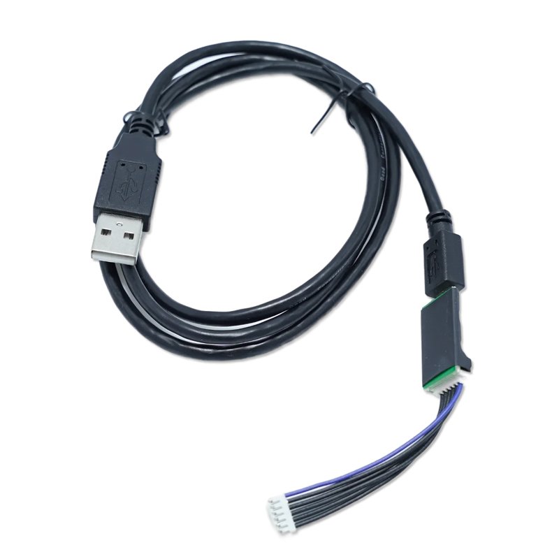
The Lobaro USB configuration adapters connects the configuration serial uart of our devices to a PC. It is used for:
- Sensor initial configuration, e.g. network parameters like LTE APN point
- Viewing firmware log/debug diagnostic output
- Firmware updates
- Powering some of our devices (Boot and Reset must be disconnected to use as USB power supply)
- using our free Lobaro Maintenance Tool PC software.
Adapter V1
Order-Code
The configuration adapter including a 1 m USB cable can be ordered using its article number: #8000005.
Installation
The CP2102 uart serial USB driver must be installed, it can be downloaded at the Silicon Labs Homepage.
- CP210x_Universal_Windows_Driver.zip for Windows 11+
- CP210x Windows Drivers v6.7.6 for Windows 10 and earlier
Physical connection
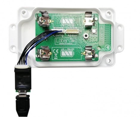
Connect your Lobaro Device to the USB-port of your computer using the Lobaro Config Adapter. The 6-pin connector must be plugged into the white rectangular socket on the device that is labeled with the word CONFIG. The location of the socket is dependent on the specific device and hardware version you are trying to attach. See the hardware specific product description for the individual connector location.
Some devices can be powered by the 3.3V the config adapter can provide out of the USB Port. Other devices, mostly the NB-IoT/LTE-M enabled cellular IoT boards or the need their normal power supply connected as well. If in doubt, just make sure you have the device powered!
Schematic
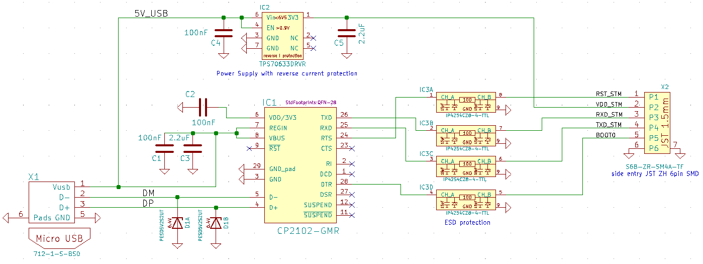
Connector Type
The USB adapter uses a six-wire JST-ZH series connector for attaching to Lobaro hardware at the config connector.
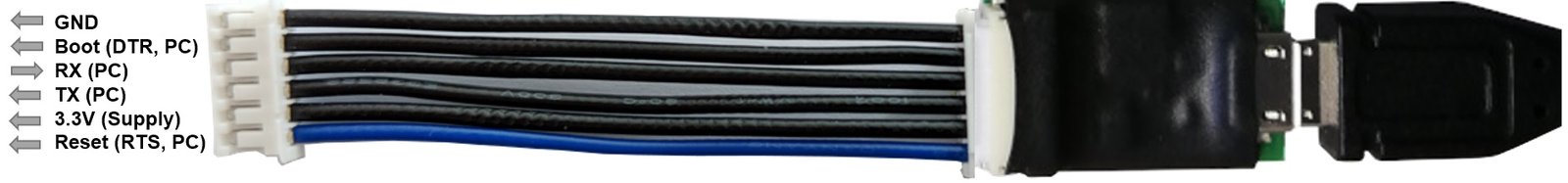
Control Lines
- Boot0 of Lobaro sensors is connected to DTR line of the PC uart
- Reset (active low) of Lobaro sensors is connected to RTS line of the PC uart
Normally the handling of these uart control lines is done automatically by the Lobaro PC tool. When using an alternative uart terminal tool make sure you setup the RTS and DTR lines correctly or simply cut the DTR/RTS wires from the USB adapter if the reset and/or bootloader control lines are not needed and you simply want to look at the devices log output.
DTR control line
- Low / true => Run Firmware after Reset (Default since BOOT0 has internal pull-down)
- High / false => Run Bootloader after Reset
RTS control line
- High / false => Run Firmware / Bootloader (Default since RESET has internal pull-up)
- Low / true => Chip in RESET mode (not running)
Adapter V2
The usb adapter in version 2 will be available latest end of 2024.